48+ Half Wave Bridge Rectifier Diagram UK. Connecting to the online market place is one of the gruff cuts to do. In full wave bridge rectifier, an ordinary transformer is used in place of a center tapped transformer.
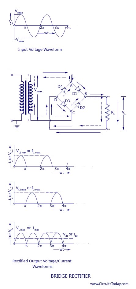
In half wave rectifier, we remove the negative half cycle of ac wave by using one diode, while in full wave rectifier we convert the negative half cycle of ac into positive cycle using 4 diodes.
The bridge rectifier is an electronic component that is widely used to provide full wave rectification and it is possibly the most. A zero degree firing angle alpha is represented by 0 ms, a 45° is 2.5 ms (2500 µs), a 90° is 5 ms (5000 µs) and 135° is 7.5ms. The efficiency, ripple factor, average value, rms value all are same except the. Half wave rectifier, 2.full wave rectifier 3.
Komentar
Posting Komentar