12+ Half Wave Bridge Rectifier Circuit Images. The advancement of rectifiers has invented various approaches in the domain of power electronics. An hwr (half wave rectifier) circuit is the one that allows only one cycle of input of the ac signal and blocks the other.
The circuit uses four diodes d1, d2, d3 and d4 connected in the form of bridge.
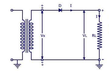
Full wave bridge rectifier circuit. An hwr (half wave rectifier) circuit is the one that allows only one cycle of input of the ac signal and blocks the other. Half wave rectifiers switch between being. It uses both halves of the waveform in the transformer winding and as a result reduces heat losses for a given level of output current when compared to other solutions.
Komentar
Posting Komentar